The clean agent system typically installed for the fire protection shall be Total Flooding High Pressure type, utilizing a fixed pipe and nozzle distribution network.
Fire Suppression System for the Protected area shall have two banks of the Inergen high-pressure storage cylinders, one bank selected as ‘Main’ and the other bank as ‘Reserve’.
The quantity of ‘Reserve’ agent supply shall be the same as the quantity of ‘Main’ supply.
All the cylinders both “Main” as well as “Reserve” shall be installed inside the inergen cylinder room or shelter.
For single area of protection individual banking arrangement is considered and for multiple protected zones central banking method is considered, where activation of individual zone shall be achieved by means of directional valves.
The intervention of the system is activated automatically by fire smoke detectors, which will sense the fire in the protected room and send signals to FACP which will actuate the solenoid mounted on the master cylinder, and locally by manual release station.
In emergency, the system can be activated by operating Lever release actuator mounted on the master cylinder of the clean agent storage unit.
The intervention of the master cylinder will actuate the opening of all slave cylinders, the release of gas will activate the alarm signal, by pressure switch, which will then be displayed on the FACP. A pre-alarm signal from FACP will be power the sounders inside the protected room.
Automatic Operation of Inergen System
The Auto/Manual switch on the each exit of protected area shall to be set in auto mode.
All devices and systems of the clean agent Fire Suppression System shall be monitored and controlled by a fire alarm control panel FACP.
FACP shall initiate alarms, shutdown signals and the release of fire suppression agent in the respective protected area.
This control system is capable of being in operation for 24 hours even in the event of loss of power and shall comply with requirements of NFPA 70 standard.
In case of fire, the activation of any smoke detector or heat detector senses a fire in the protected area shall sent a signal to the FACP.
Then FACP begins a series of programmed actions starting with sounding an alarm.
When two detectors on both detection circuits are activated simultaneously, then FACP shall send an actuation signal to the electric actuator, actuating the pilot cylinder set and opens the specific valve automatically.
The discharged back pressure gas from the master cylinder shall actuate the specific directional valve and, thereafter, shall activate the specific number of clean agent cylinders for the hazard area.
Number of clean agent cylinders to be activated shall be determined, depending on the location of manifold check valves.
Upon the activation of Inergen cylinders, the inergen gas is discharged through the manifold, directional valve header, directional valve which is already in open condition and by the distribution piping in the protection area.
During this process, a part of the clean agent gas, which passes through the directional valve will activates the pressure switch, which in turn causes a gas discharge signal to be sent to the FACP.
System Operation by Operating Manual Release Station
The Auto/Manual switch on the each exit of protected area shall to be set in manual mode.
In case of fire, the manual release station provided shall be operated for clean agent release.
Upon receipt of an actuation signal from the manual release station for clean agent release, the FACP will generate an alarm siren.
Based on a pre-set time delay, the inergen control panel shall send an actuation signal to the solenoid on the master cylinder and the specific directional valve actuating cylinder set.
The discharged back pressure gas from the master cylinder shall release the specific directional valve and, thereafter, shall activate the specific number of clean agent cylinders for the hazard area.
Number of clean agent cylinders to be activated shall be determined, depending on the location of manifold check valves.
Upon the activation of Inergen cylinders, the inergen gas is discharged through the manifold, directional valve header, directional valve which is already in open condition and by the distribution piping in the protection area.
During this process, a part of the clean agent gas, which passes through the directional valve will activate the pressure switch, which in turn causes a gas discharge signal to be sent to the FACP.
OPERATING ALARMS AND INDICATORS
Audible and visual pre-discharge alarms within the protected area will give positive warning of impending discharge.
The operation of the warning devices shall be continued after agent discharge until positive action has been taken to acknowledge the alarm and proceed with appropriate action.
Abort switches shall be located within the protected area and shall be located nearer to the means of egress for the area.
Operation of the abort function shall result in both audible and distinct visual indication of system impairment.
The abort switch shall be clearly recognizable for the purpose intended.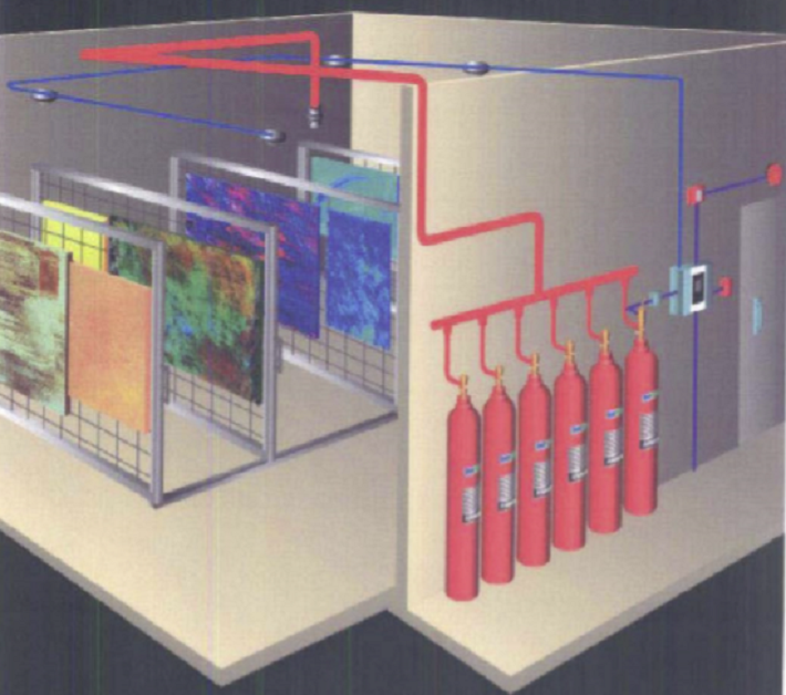
Alarms indicating failure of supervised devices or equipment will give prompt and positive indication of any failure and will be distinctive from alarms indicating operation or hazardous conditions.
The Protected room shall have manual release stations for the release of fire suppression agent, one located nearer to the exit of each personnel exit door.
Status panel’s c/w auto / manual switch shall be located near exit of protected room.
The status panels shall be labelled 4 lamp units to indicate Auto/Manual, Inhibit & Discharge.
Routine Maintenance of Inergen Fire Suppression System
This section of the maintenance procedure should be read in conjunction with the relevant approved drawings.
To ensure that each Inergen System will function as intended, a regular maintenance program should be established.
Following tasks should be carried out on each Inergen System in turn.
Weekly:
A visual check of the Inergen system should be undertaken once per week to ensure that there are no signs of physical damage or corrosion.
The pressure gauge reading should be checked on each Inergen Cylinder.
Nominal filling pressure of each cylinder is 200 Bar at 15°C but the pressure indicated will vary according to the ambient temperature of the place where the cylinders are located.
If a cylinder shows a loss of pressure of more than 5% when checked in conjunction with the Temperature Correction Graph, it must be removed and replaced with a full one.
If it is found necessary to replace one or more Inergen Cylinders, carry out the procedure described in the operating manual section entitled ‘After a Fire’.
Record inspection and maintenance each time it is carried out.
Six-Monthly:
The pressure gauge reading should be checked on each INERGEN cylinder as mentioned in weekly checks.
Check the discharge hose and actuation hoses are fitted properly, and check joints for tightness.
Carry out examination of the complete Inergen system.
Check everything is in good order and nozzles in the correct position and not obviously blocked.
ANNUAL MAINTENANCE EXAMINATION
Systems shall be maintained at regular intervals, not more than one year apart, or when specifically indicated by an inspection.
(Exception: Cylinder pressure must be checked every six months per NFPA 2001.)
Maintenance is a “thorough check” of the system. It is intended to give maximum assurance that a system will operate effectively and safely. It includes a thorough examination and any necessary repair, recharge, or replacement.
It will reveal if there is a need for hydrostatic testing of the cylinder.
The procedures listed in this section are the minimum that is necessary to maintain a system, if circumstances warrant them, a more thorough procedure should be followed to assure system performance.
Make certain that all people affected by the maintenance are informed before you start, this may include the owner, security personnel, the local Fire Department, and possibly local workers that may be affected by equipment shutdown or start up.
If the system includes an ANSUL AUTOMAN II-C releasing device, before proceeding with annual maintenance examination, insert lock pin in ANSUL AUTOMAN II-C release and remove nitrogen cartridge. Install safety shipping cap on cartridge.
1. Survey the hazard to make certain it has not changed from what the system was designed to protect. While surveying the hazard, look for different fuels, loss of hazard integrity, new hazards, etc.
2. Check all nozzles to make certain they are in place, that the orifice plates are in place and with the proper orifice. Check the condition of the nozzle for corrosion or damage and make certain it is not obstructed internally or externally.
3. Check the condition of the piping to make certain that it is properly secured in the hangers and that all fittings are connected tightly.
4. Check all warning nameplates throughout the area. Make certain they are in place, mounted securely, readable, and are not damaged.
5. Check all cylinder bracketing. Make certain all cylinders are secured in the brackets. Check for corrosion, damage, or missing components.
6. Check the condition of all cylinders. Look for signs of damage or corrosion, and check the cylinders last hydrotest date. (NFPA 2001 states “Cylinders continuously in service without discharging shall be given a complete external visual inspection every five years or more frequently if required.
The visual inspection shall be in accordance with Compressed Gas Association Pamphlet C-6, Section 3; except that the cylinders need not be emptied or stamped while under pressure.”) Using the Pressure Test Gauge Assembly (Part No. 427953 for CV-98 valves), check each cylinder to determine if pressure is within the acceptable range.
See Pressure Correction Chart in the Appendix Section. To use the pressure test gauge assembly, first make certain cylinder is properly bracketed. Before attaching assembly, make certain stem is completely backed out by turning hand wheel counterclockwise until it stops.
Attach the assembly to the fill inlet port of the INERGEN cylinder valve. Wrench tighten. To read the cylinder pressure, turn handwheel completely clockwise until it stops, then back it off 1/4 turn. This will open the fill port. After pressure has been read, close fill port by turning handwheel completely counterclockwise.
Slowly loosen the adaptor nut to remove the pressure test gauge assembly from the fill port. While removing this, you may hear a small hiss of pressure remaining in the assembly. This is normal and will not last long. You will also notice the gauge pressure will drop to zero.
Record the cylinder pressure for reference on the next pressure test. Visually note the location of the indicator needle on the cylinder valve to determine if it is in close proximity to the actual reading of the test gauge.
7. Check condition of all cylinder discharge hoses. Look for signs of structural problems like abrasions or weather checking. Make certain all hoses are connected properly. All hoses must be tested every 5 years. Refer to NFPA 2001 for detailed testing requirements.
8. Check condition of all actuators by completing the following:
a. Remove all actuators from the cylinders and leave them off until the final step in the Maintenance Section.
b. For manual actuators, check the condition of each actuator to make certain they operate freely. When finished, reset them and seal with inspection seals as required. Do not install on cylinder valves.
c. For electric actuators, check to make certain all wires are properly connected. Do not install on cylinder valves.
9. Check the condition of the orifice union and make certain correct size orifice plate is in place. Orifice size can be read on exposed tab.
10. Check all pressure switches for signs of damage or corrosion. Make certain piping to switch is properly attached.
11. Check all switches on the system to assure they will operate properly. These may include maintenance switches, abort switches, main/reserve switches, etc. When completed, make certain they are all set in the correct position.
NOTICE: Before proceeding with Step No. 12, make certain all electrical actuators have been removed from all cylinder valves and that the cartridge has been removed from the ANSUL AUTOMAN II-C releasing device(s) if part of the system.
12. Check condition of control panel for tampering, corrosion, or damage. Test panel at this point by referring to the appropriate AUTOPULSE Control System Manual.
13. Check all detectors. Make certain they are in place, clean, and not damaged. If required, check the sensitivity of each per the instructions of the detector manufacturer. See appropriate AUTOPULSE Control System Manual for detailed operating instructions of the panel.
14. Check all pull stations. Make certain they are in place, that they are not blocked or damaged. Operate each pull station to make certain that they operate the control panel. Reset each pull station and seal with visual inspection seal.
15. While checking the detectors and electric pull stations, inspect each alarm device. Check the alarms condition and verify that it operates properly when energized. Reset the alarm circuit after each test.
16. If the system includes an ANSUL AUTOMAN II-C releasing device, test it per the instructions titled Thermal Detection/Electric ANSUL AUTOMAN II-C Release listed in this section. If system contains a cable pull station, check it for correct operation at this time. Reset and reseal after operating.
17. Reset the entire system. This includes the control panel, all actuators, detectors, alarms, actuator cartridge, release cartridge, and pressure switches. After all components have been reset, install actuators back on to the cylinder valves.
18. Record that the maintenance has been performed as required by the Authority Having Jurisdiction. Notify all personnel that the maintenance has been completed and the system is back to normal.
Resetting and Recharging
CLEAR ELECTRICAL EQUIPMENT Refer to AUTOPULSE installation, operation, and maintenance manuals for detailed instructions on resetting the electric detection system.
NOTICE: If AUTOPULSE Control System is utilizing an ANSUL AUTOMAN II-C releasing device for pneumatic actuation, AUTOPULSE panel will remain in trouble condition until ANSUL AUTOMAN II-C release is recocked.
If utilizing an ANSUL AUTOMAN II-C release with thermal detectors, detectors must be cooled down, below their set point, before release can be reset.
Refer to ANSUL AUTOMAN II-C Installation, Operation, and Maintenance Manuals, Part No. 17788 and 31496, for detailed instructions.
CHECK ELECTRICAL AND MECHANICAL EQUIPMENT
Piping and Nozzles
A fire condition could cause damage to the piping and nozzles and possibly support members.
Check all rigid pipe supports and all fitting connections.
Take the nozzles off the piping, inspect for damage, corrosion, or obstructions, clean and re-install.
Selector Valve
NOTE: When actuators are removed to be reset, the selector valve will automatically reset itself.
Reset the selector valves by completing the following steps:
1. Reset HF actuator and booster actuator. Refer to resetting instructions.
2. If necessary, reset lever actuator on top of selector valve. If required, replace pin and reseal with lead wire seal, Part No. 197.
Electric Detection System
ANSUL AUTOMAN II-C RELEASING DEVICE – For complete resetting instructions, refer to Installation, Operation, and Maintenance Manuals, Part No. 17788 and 31496.
AUTOPULSE CONTROL SYSTEM – For complete resetting instructions, refer to the appropriate installation, operation, and maintenance manual.
Pressure Switch
Reset the pressure switch by completing the following steps:
1. Make certain all pressure in the line to the switch has been properly relieved.
2. Push in red knob on end of pressure switch plunger.
3. Make certain electrical function has been correctly reset.
Resetting the HF Actuator
The HF actuator must be reset after each use. An arming tool, Part No. 75433, is required. To rearm, complete the following steps:
1. Remove electrical power to the HF actuator.
2. Remove the actuator from the CV-98 valve or the selector valve.
3. Using the arming tool, Part No. 75433, push up on the actuator pin located at the bottom of the actuator. The actuator pin will be locked in the armed position when a “snap” is heard.
4. Do not reinstall actuator until booster actuator is reset.
Resetting the Booster Actuator
The booster actuator must be reset after each use. A reset tool, Part No. 429847, is required. To reset, complete the following steps:
1. Remove the booster actuator from the CV-98 valve or the selector valve.
2. Make certain the internal threaded plug in the reset tool, Part No. 429847, is backed out approximately half way.
3. Hand tighten the reset tool into the bottom of the booster actuator.
4. Turn the internal threaded plug of the reset tool clockwise (into the booster actuator) until a “snap” is heard.
5. Back out the internal threaded plug one to two turns.
6. Unscrew the reset tool from the booster actuator.
7. Check to confirm that it is reset properly: the top pin of the booster actuator will be approximately flush with the top of the actuator. The bottom pin will be flush with the inside surface of the actuator.
Once both the HF actuator and the booster actuator are reset, reinstall both and restore electrical power to the system if all other recharge steps have been completed.
PLACE SYSTEM BACK IN SERVICE – CV-98 VALVE
Recharge procedures for cylinder assemblies utilizing the CV-98 valve with an HF electric actuator requires normal cylinder recharging.
RECHARGE CYLINDER
The following steps must be followed when removing discharged cylinders from the system:
1. Disconnect the flex bend from the cylinder(s) outlet.
2. Remove all actuators from the cylinder valves.
3. If necessary, remove 1/4 in. actuation hose, elbow, and adaptor from pneumatic actuation port.
4. If necessary, install plug, Part No. 42411, into pneumatic actuation port and wrench tighten.
5. With cylinder secured in bracket, relieve any remaining pressure in the cylinder by completing the following:
a. Make certain discharge cap IS NOT on valve outlet. See Figure 1.
b. Attach bleed down device, Part No. 426028, to valve fill inlet. See Figure 2.
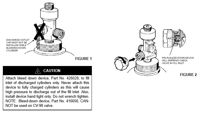
c. Bleed residue pressure from cylinder. Make certain cylinder is completely empty before removing bleed down device.
d. With cylinder completely empty, remove bleed down device and install safety shipping cap.
e. Complete Steps a. through d. on all discharged cylinders, both pilot and slave.
6. Determine if discharged cylinder requires hydro-testing prior to being recharged. Note last hydro date on cylinder collar.
If cylinder does not have a star stamp (350/425/435 cu. ft. INERGEN cylinders), it requires hydro 5 years from last hydro date.
If cylinder has a star stamp (200/250 cu. ft. INERGEN cylinder), it requires a hydro-test 10 years from last date.
NOTICE: Empty cylinders must be sent to an authorized Ansul recharge facility for filling. Contact Ansul Technical Services Department for any information needed concerning authorized fillers in your locality.

