Below are general guidelines that cover the operation and maintenance instructions for Purafil H2S Scrubber to ensure trouble free operation.
The page provides all the necessary technical data for operation, maintenance and precautionary measures to be taken for providing proper operation guidance for the end user personal.
THE PURAFIL DEEP BED SCRUBBER (DBS) is designed for areas where high contaminant gas levels are present.
It provides protection against high concentration of toxic gases.
The DBS is ideal for refineries, steel mills, smelters, chemical plants, petrochemical plants, and other hostile environments.
To control Specific contaminant gases, the DBS is filled with up to three different dry scrubbing media manufactured by Purafil, Inc.
Each media type effectively removes a range of contaminant gases for maximum protection.
Purafil Puracarb media which target at maximum removal of H2S is used in the DBS. With the selected media and design, we can achieve 99.5% removal efficiency.
Equipment’s are selected to provide less than 25 ppb at exit for average inlet H2S of 20 ppm challenge.
Media can withstand surges of high H2S up to higher ppm while maintaining a gas removal efficiency over 99.5%. Such surges will consume faster the media.
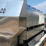
Purafil Deep Bed Scrubbers are with redundant (Duty & Stand by) blowers and are constructed of Stainless-steel Grade 316 gauge 14 for internal frames and panel inner/outer pans and extruded aluminum for external frame, in double pan Polyurethane insulted construction and weatherproofed.
Housing designed for horizontal airflow with top discharge.
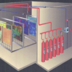
Housing equipped with Prefilter and final filter sections with aluminum tracks with nylon piles and gasket side access doors, three consecutive 12” deep passes for bulk fill of chemical media (total media beds 36”) with top media fill ports & bottom side media emptying ports, redundant (duty & stand-by) blowers section with backdraft dampers upstream and downstream blowers and an isolation panel separating blowers, in draw through arrangement with side access doors, VFD, pressure tapings across pre-filter & final filter, legs channels and anchoring holes.
Servicing access is through side access doors on both sides for filters and blower section with a clearance of 30”.
Media can be accessed through fill ports at top and emptying top at bottom of side panels.
General Design Parameters and Design Conditions
Pre-filter are designed for 30% efficiency (Ashrae Std 52.1), UL Class2
Gas is passed through the chemical media.
Three consecutive passes of 12” (305mm) depth, a total of 36” beds, for bulk fill media type Puracarb, having 20% removal capacity by weight on H2S (i.e. 100lbs of media removes 20lbs H2S).
Media is UL Class-2 flammability rated.
Final filterJFL90 is designed for 90% efficiency (Ashrae Std 52.1), UL Class 1.
Blower section are with side access doors on both sides housing duty and stand-by direct driven blowers/motors assembly in stainless steel 316 with mild steel wheels and backdraft dampers sections upstream and downstream blowers.
An isolation panel separates both blowers’ compartments.
Blowers are rated for the required air volume and TSP to overcome filters resistance plus 2.50” wg External Static pressure for ductwork.
Motors TEFC, Class B Insulation, 50◦C ambient, 415/3/50 voltage, supplied with VFD-variable frequency drive.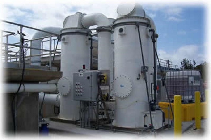
Blower drives are EZ Plenum fans from Mechanoent Corporation.
EZ Plenum fans are in 316 stainless steel construction with ECF-9, wheels in mild steel. These are direct drives which are designed to give AMCA performance class 2.
Motors from WEG motors are of Class F with IP55 rating.
Please refer the original catalogs for the complete technical data of the motors of each DBS unit.
ALTIVARTM Series 212 Variable Speed Drives for 3-phase asynchronous motors are used. ALTIVARTM drive includes 3 logic inputs, 2 analog inputs, 1 analog output and 2 relay outputs (with 1 NO and 1 NO/NC contacts), LED display, 4 digits-7 segments, with 7 button keypad and RJ45 Modbus port, removable terminal block for software and selectable BacNet, ModBus, METASYS N2 or APOGEE P1 communication protocols.
Please refer to the original catalogue for the complete data specification of the ALTIVAR 212.
For monitoring pressure drop across filters, pressure tapings are provided across Pre filter and final Particulate filter for pressure monitoring devices – dial gauges for local reading of delta-p and pressure transmitters 984M Differential Pressure Transmitters from Beck Germany are used. These transmitters use Piezoresistive pressure transducer technology.
Transmitters are selected in range of 0-250 Pa across pre filter and 0-500 pa across final filter with 85mm Dia.
Gage housing with process connection P2 is made from ABS, mounting part with process connection P1 is made from POM.
Transmitter has digital display, 3 wires connection, 24 VDC/AC power supply and configurable 0-10 V/4-20 mA output with adjustable transistor switching output with a maximum switching capacity of 35 VDC/100 mA, complete with Climasel kit consisting of 2m PVC hose and 2 plastic pipes.
P1 and P2 connections connect to pressure tapings provided on the DWDBS housing.
The transmitters Conform to Standards EN60770, EN61326 2002/95/EEC (RoHS).
Purafil systems and media are manufactured in compliance with, and certified, ISO 9001.
All systems are subjected to standard factory inspection based on an Audit Check List and acceptance criteria.
Detailed Precautionary Measures
Before commencing any task, give careful consideration to what is or maybe involved; the extent of the plant / equipment requiring attention and how your intended activities may affect others working in the vicinity.
If an accident occurs details must be entered in the Clients accident report book and submitted immediately to the Client.
It is the client’s responsibility to provide a system for the reporting of injuries, diseases and dangerous occurrences.
Copies of a suitable occurrence report from must be freely available for use.
A “Permit to Work” system to be implemented.
Working on ‘Live” equipment is not recommended.
Person working on the equipment should read the original service manual before any maintenance.
The service manual should be retained with the unit because it contains information necessary for proper maintenance. There is a pocket envelope provided for this purpose. Attach it permanently to the unit.
Keep all nuts, bolts and screws tight to be sure the equipment is in safe working condition.
CAUTION:
All personnel involved with electrical installations, operation and maintenance should be well-informed and up to-date concerning the safety standards and principles that govern the work and carefully follow them.
Before work commences, it is the responsibility of the person in charge to ascertain that these have been duly complied with and to alert his personnel of the inherent hazards of the job in hand.
It is recommended that these tasks be undertaken only by qualified personnel and they should be instructed to:
- Avoid contact with energized circuits or rotating parts,
- Avoid by-passing or rendering inoperative any safeguards or protective devices.
- Avoid extended exposure in close proximity to machinery with high noise levels.
- use proper care and procedures in handling, lifting, installing, operating and maintaining the equipment, and follow consistently any instructions and product documentation supplied when they do such work.
- Before initiating maintenance procedures, be sure that all power sources are disconnected from the motor and accessories to avoid electric shock.
- Firefighting equipment and notices concerning first aid should not be lacking at the job site; these should be visible and accessible at all times.
- Never enter an enclosed blower cabinet or reach into housing while fan is running.
- The motors in PURAFIL® equipment get very hot. This is normal and should not be regarded as a problem with the motor. However, take special care to avoid touching the hot area.
SPECIAL PRECAUTIONS
DISPOSAL
PURAFIL® media is a non-toxic, non-flammable substance. Filtration of contaminants through PURAFIL® media causes molecular changes to occur, and the resulting product is usually not harmful to the environment.
Although special precautions are generally not required when disposing of spent media, government regulations may require specific disposal procedures if the resulting product could be harmful to the environment.
Large quantities of PURAFIL® media should not be disposed of in dumpster-like equipment because the weight of the media could cause difficulties in handling the dumpster.
Independent laboratory analysis for Environmental Protection Agency toxicity characteristics may be required if the contaminants eliminated from your environment include heavy metals and pesticides.
INHALATION
A well-ventilated work area is suggested for changing the PURAFIL® media, as dusting occurs in fresh media due to handling abrasion.
Workers should avoid direct inhalation of considerable PURAFIL® dust, as it induces sneezing.
In closed, unventilated spaces, dust masks such as the 3-M No. 8500 are suggested.
WATER
Avoid exposing the PURAFIL® media to water or precipitation, as this dissolves permanganate content.
Storage of media should be in a dry place with less than 95% relative humidity.
Exposure of permanganated solution to the skin causes brown staining which is temporary and not harmful.
This staining can be removed by washing in a diluted solution of water and sodium bisulfite.
EYE CONTACT
If dust is exposed to the eyes or delicate membrane, flush thoroughly with water and seek treatment by a physician. Follow normal procedures for exposure to abrasive dust.
Trouble Shooting Check List with Remedies
| Deep Bed Scrubber | |||
| Symptoms | Problem | Checks\remedy | |
| Particulate filters | Improper particulate filter gage reading | Heavily soiled particulate filters | Was a sacrifice final filter used during the first few minutes of operation and then replaced by the specified filters? |
| Media Bank | Airflow too low | Perforated surfaces may be clogged Filters loaded | Vacuum or blow off with compressed air
Replace filters |
| PURAFIL media pellets | Found in unit (outside vertical media banks) | Check perforated screens for ruptures | Replace the ruptured perforated sheets |
| Direct Drive Blowers Assembly | ||
| SYMPTOM | PROBLEM | CHECKS/REMEDY |
| Rubbing sound coming from blower section | Wheel rubbing cone | Check wheel and cone clearance. Retighten weld nut screws. Check security of weld nut. |
| Motor seems to be running too slowly. | Electrical connections may be incorrect. | Have an electrician compare the connections with the Manufacturer’s instructions. |
| Motor seems to be too hot | same as above | same as above |
| Purafil Dwyer Gases | ||
| Symptom | Problem | Checks/Remedy |
| Sluggish readings | Duplicate pressure port not plugged | Plug Pressure Port |
| Diaphragm damage due to over pressure | 15psi maximum | |
| Fittings or sensing lines are blocked or pinched | Repair is required | |
| Cover is loose or “O” ring is damaged or missing | See Section 3.5 in PPU Service Guide | |
| Ambient Temperature is too low (20ºF) | Order special low temperature gages | |
| Gage can’t be erode (set) | Pointer stuck | Pointer should not be touching scale |
| Spring/magnetic assembly should not be touching helix | ||
| No metallic particles should be clinging to magnet | ||
| Cover zero adjustment should be properly engaged in adjusting screw. | ||
WEG MOTORS TROUBLESHOOTING |
||
| Failure | Problem cause | Corrective measures |
| Motor fails to start | No voltage supply
Low voltage supply Wrong control connections Loose connection at some terminal lug overload |
check feed connections to control system and from this to motor
check voltage supply and ascertain that voltage remains within 10% of the rated voltage shown on the motor nameplate. Tighten all connections Try to start motor under no-load conditions. If it starts, there may be an overload condition or a blocking of the starting mechanism. Reduce load to rated load level and increase torque. |
| High noise level | Unbalance
Distorted shaft Incorrect alignment Uneven air gap Dirt in the air gap Extraneous matter stuck between fan and motor casing Loose motor foundation Worn bearings |
Vibrations can be eliminated by balancing rotor. If load is coupled directly to motor shaft, the load can be unbalanced
Shaft key bent; check rotor balance and eccentricity Check motor alignment with machine running. Check shaft for warping or bearing wear Dismantle motor and remove dirt or dust with jet of dry air Dismantle motor and clean. Remove trash or debris from motor vicinity. Tighten all foundation studs. If necessary, realign motor Check lubrication. Replace bearing if noise is excessive and continuous. |
| Overheating of bearings | Excessive grease
Excessive axial or radial strain on belt Deformed shaft Rough bearing surface Loose or poorly fitted motor end shields Lack of grease Hardened grease cause locking of balls Foreign material in grease |
Remove grease bleeder plug and run motor until excess grease is expelled.
Reduce belt tension Have shaft straightened and check rotor balance Replace bearings before they damage shaft Check end shields for close fit and tightness around circumference. Add grease to bearing. Replace bearings. Flush out housings and relubricate. |
| Intense bearing vibration | Unbalanced rotor
Dirty or worn bearing Bearing rings too tight on shaft and/or bearing housing Extraneous solid particles in bearing |
Balance rotor statically and dynamically
If bearing rings are in perfect condition, clean and relubricate the bearing, otherwise, replace bearing Before altering shaft or housing dimensions, it is advisable to ascertain that bearing dimensions correspond to manufacturer’s specifications Take bearing apart and clean. Reassemble only if rotating and support surfaces are unharmed |
| Overheating of motor | Obstructed cooling system
Overload Incorrect voltages and frequencies Frequent inversions Rotor dragging on stator Unbalanced electrical load (burnt fuse, incorrect control) |
Clean and dry motor; inspect air vents and windings periodically
Check application, measuring voltage and current under normal running conditions. Compare values on motor nameplate with those of mains supply. Also check voltage at motor terminals under full load. Exchange motor for another that meets needs. Check bearing wear and shaft curvature. Check for unbalanced voltages or operation under single-phase condition. |
MAINTENECE CHECKLIST
| S.No | Tag No. | Duration | Last Attempt/Remarks |
| 1 | Reading on Pressure transmitters pre filter – | PA | |
| 2 | Media Life as per Media test report First Pass | Months | |
| 3 | Media Life as per Media test report second Pass | Months | |
| 4 | Media Life as per Media test report third Pass | Months | |
| 5 | Reading on Pressure transmitters Final filter – | PA |
Based on the above reading following Preventative Maintenance needs to be performed.
- If the reading for the Pre-filters is higher than the maximum limit which is 249 Pascal the Pre-filters needs to be replaced.
- Based on the media life report of each pass if the media life is close to 0 months the media needs to be replaced.
- If the reading for the Final -filters is higher than the maximum limit which is 299 Pascal the Final-filters needs to be replaced.
REPLACEMENT PARTS AND MATERIALS
While Purafil, Inc. products are built with durability, some parts of the PURAFIL® unit will require replacement during the normal lifetime of the equipment. Replacement items may be ordered from your local PURAFIL® representative or from Purafil, Inc.
Consumables: In order to maintain proper performance levels, particulate filters and PURAFIL® media must be replaced periodically, as they have a finite life. (See the Media Sampling Service Guide)
Gages: No lubrication or periodic servicing is required. The gage unit cover and housing should be kept clean, however solvents are not recommended as a cleaning agent, as they will fog the cover. Occasionally disconnect pressure lines to vent both sides to the atmosphere; the re-zero (set) the gage. (See Gage Unit Service Guide)
Moving Parts: Bearings, sheaves, motors, belts, etc. are all subject to gradual deterioration and/or sudden breakdown. (See Blower Assembly Service Guide)
MEDIA REPLACEMENT
PURAFIL® engineered dry-chemical media has a finite life. Our media contains special active ingredients that react with odors and gaseous pollutants to remove them from the airstream.
Once the active ingredients are spent, it is time to replace the media in your system. After start-up, your local PURAFIL representative will work with the owner to periodically secure media samples.
Purafil, Inc. will provide regular laboratory analysis of such samples to establish life cycles.
Note, color change of media does not indicate level of remaining life.
Since every installation varies due to the type and quantity level of the contaminant, each operator must develop a sample schedule best suited to their system.
However, until a schedule can be established, we recommend that a sample is taken from each vertical media bank and sent for analysis, so that a replacement date can be projected with a recommended sampling schedule.
Media Life Analysis (MLA) is a complimentary Purafil, Inc. service. MLA Sample Kits are available through Purafil, Inc. If analysis reveals that it is time to replace the media, order the appropriate pounds of media required per module used in the unit.
See Media Sampling Service Guide for instructions on how to take a media sample from your unit.
MEDIA LIFE ANALYSIS SAMPLING INSTRUCTIONS
The Media Life Analysis (MLA) Sampling Kit should be used to sample one PURAFIL dry scrubbing system. For example, if you have a two-pass system, prepare and return two sample bags, gather one for each pass.
Additional bags can be stored for further use.
Complete the Transmittal Form. Include the detailed information listed on the UNIT NAMEPLATE on the Media Sample Analysis Transmittal Form and the Media Sample Bags which are also enclosed with units.
PURAFIL MEDIA SAMPLING PROCEDURE:
For Bulk Fill Systems:
Using the last three (3) inches of each twelve (12) inch bed, insert the sample probe halfway down into the bed for samples.
Continue this procedure until the sample bag is filled.
Mark the bag with the following information from the Unit Nameplate:
- Sales Order (S.O.) No.
- Serial No.
- Unit Type.
Also, indicate which bed or pass this media is from: #1, #2, #3, etc.
Return the completed Media Sample Transmittal Form and filled Media Sample Bags using the enclosed envelope.
For more detailed instructions, please refer to the service guide for media sampling.
Purafil media transmittal is attached with the document.
| SAMPLING SCHEDULE | |||||
| Date sample taken | Sampled bank\unit | Estimated expended life | Next sampling date recommended | Projected replacement date | Start-up date/other |