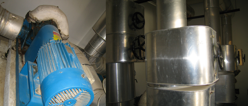
Purpose of this documents is to establish a standard procedure for the proper operation and maintenance of chilled water pumps.
This HVAC procedure will also serve as guideline for newly hired employees maintenance or facility management department who will be dealing with chilled water pump unit operation and maintenance activity.
Scope of this standard covers all Chilled Water Pumps which can be under an A/C maintenance contract and the construction projects as well.
It is the responsibility of the A/C maintenance technician to properly operate and maintain chilled water pumps. Maintenance personnel should be competent enough to operate and maintain these equipments to avoid any malfunction or downtime to equipment due to breakdown. The FM supervisor and the maintenance engineer should assure that this maintenance procedure will be followed.
Brief Description of Chilled Water System
Chilled water pump is used to circulate the chilled water in the piping system that is going to the Chiller Unit.
CWP Chilled water pump drives the flow of water from the return pipeline going to the evaporator shell of the Chiller Unit.
Periodic checking of chilled water pump should be done to assure continuous flow of water into the pipeline.
Chilled Water Pump Operation Procedure
Start-up
Prior to start-up, make sure that the suction and discharge valve of the chilled water pump is normally open.
Make sure that the circuit breaker is energized.
Turn the power switch ON and check if the pump rotates in correct direction, correct direction is clockwise, viewed from the motor end of the pump.
If the motor rotates in the reverse direction, switch OFF the unit and interchange one of the motor terminal lead of power supply terminals.
Open air vent if necessary to release excess air in the system.
Shutdown Procedure
Switch OFF the unit.
If the unit shall be switch OFF for a long time, de-energize the circuit breaker.
CHILLED WATER PUMP MAINTENANCE PROCEDURE (ANNUALLY)
Wear safety goggles, hand gloves and safety shoes when conducting this maintenance procedure.
Change-over chilled pump unit to stand by unit.
Switch OFF the chilled pump unit to be maintained.
De-energize the circuit breaker of the unit to be maintained.
Follow the following items during inspection:
| Inspection Item | Inspection Contents | Inspection Method | Criteria |
| Bearing | Temperature
Vibration Operation Sound |
Use thermometer
Use Vibration Meter Hearing |
Place thermometer on the motor bearing cover. (data should be 60° or lower)
Data produced must be within range Soft and smooth sound (No hizzing sound). Apply specified grease. |
| Gland | Temperature
Filled with water Shaft cooling water |
Touching
Visual Inspection Visual Inspection |
The gland is not warm.
Water is dripping slightly (Water is not leaking if mechanical seal) Water is dripping consecutively (The cooling water is not heated) |
| Body | Appearance
Gland Water Pan |
Visual Inspection
Visual Inspection |
The body is not corroded.
Leak water is not stagnating. |
| Accessories | Air Vent Cock | Visual Inspection | Water is not leaking.
The knob is not stuck-up |
| Impeller | Check for scaling
Deformation and damages |
Visual Inspection | The impeller does not have any scales or foreign matters.
The impeller is fixed securely. It is not abraded. |
| Shaft | Sleeve | Visual Inspection and measuring | The shaft is neither scratched nor deformed.
The shaft is balance and straight. |
| Coupling | Shock absorbing Rubber
Key and set bolts |
Visual Inspection
Visual Inspection and tapping |
The rubber is neither abraded nor cracked.
They are neither loosened nor out of position. |
| Check valve or Non Return Valve | Water dripping
Functionality Test |
Leak inspection by Visual Inspection
Water pressure checking |
Water is not leaking.
Release water and check if water pressure decreases. |
| Base | Concrete
Mounting Bolts Base Vibration Proof Mat |
Visual Inspection
Tapping Visual Inspection Visual Inspection |
The concrete is neither damaged nor cracked.
The bolts are neither damaged nor loosened. The base is neither deformed nor corroded. The mat is neither deformed nor fatigued. |
| Electrical Motor | Appearance
External Temperature Operational Sound Vibration Bearing Temperature Slide Base Base Resistance Voltage Current |
Visual Inspection
Thermometer Listening Touching Thermometer Visual Inspection Visual Inspection and tapping Megger Tester Voltmeter Clamp Meter |
No foreign matter or rust on the motor.
Check temperature, reading should be below as written on the motor name plate. Soft, smooth sound. No vibration Place thermometer on the motor bearing cover. (data should be 60° or lower) It is neither loose nor bent. The vibration proof rubber is neither abraded nor fatigued. The tightening bolts are not corroded. Line to Line and Line to Ground Reading should be normal. Check voltage. It should be +10% of the rated voltage based on the nameplate. Check current reading. It should be below the rated motor current as indicated on the nameplate. |